How Radio Waves Propagation and Frequency Allocation
First, the division of radio wave bands
The radio channel is actually a channel for electromagnetic waves to propagate in space. The propagation speed of radio waves in space is the same as that of light waves, about 3×10⁸m/s. The relationship between its wavelength, frequency, and propagation velocity is:
λ = c / f
It can be seen that there is an inverse relationship between frequency and wavelength. Therefore, radio waves can be divided by frequency or wavelength. According to the characteristics of radio wave propagation and use, it is divided into 12 frequency bands internationally, and ordinary radio communications only use the 4th to 11th frequency bands. The radio frequency bands and bands are divided as shown in the table below:
| serial number | Band name | Frequency range | Band name | wavelength range | The main purpose | |
| 1 | Extremely low frequency (ELF) | 3~30Hz | very long wave | 100 to 10 megameters | ||
| 2 | Super Low Frequency (SLF) | 30~300Hz | Ultra long wave | 10 to 1 megameter | ||
| 3 | Ultra Low Frequency (ULF) | 300~3000Hz | Extra long wave | 1 million to 100,000 meters | ||
| 4 | Very low frequency (VLF) | 3~30kHz | very long wave | 10-10,000 meters | Audio telephony, long range navigation, time stamp | |
| 5 | Low Frequency (LF) | 30~300kHz | long wave | 10 to 1 km | Ship communications, beacons, navigation | |
| 6 | Intermediate Frequency (MF) | 300~3000kHz | Medium wave | 1000~100 meters | Broadcast, ship communication, flight communication, ship port telephone | |
| 7 | High Frequency (HF) | 3~30MHz | shortwave | 100 to 10 meters | Shortwave broadcasting, military communications | |
| 8 | Very High Frequency (VHF) | 30~300MHz | Meepo | 10 to 1 meter | TV, FM radio, radar, navigation | |
| 9 | Ultra High Frequency (UHF) | 300~3000MHz | decimeter wave | microwave | 10 to 1 decimeter | TV, radar, mobile communication |
| 10 | Ultra High Frequency (SHF) | 3~30GHz | centimeter wave | 10~1cm | Radar, relay, satellite communication | |
| 11 | Extremely High Frequency (EHF) | 30~300GHz | mmWave | 10~1mm | Radio astronomy, satellite communications, radar | |
| 12 | to high frequency | 300~3000GHz | Smeepo | 10 to 1 silk rice |
The propagation of radio waves
The propagation modes and characteristics of electromagnetic waves in different frequency bands are different, so their uses are also different. There are three main modes of propagation of radio waves:
1. Ground waves propagating along the ground:
Medium and long waves are suitable for ground propagation. The conductive properties of the earth's surface are relatively stable, and the propagation of medium and long waves is relatively stable. Among them, long waves have longer wavelengths, have stronger diffraction ability when encountering obstacles, and have longer transmission distances. They are mostly used for navigation.
2. Sky waves propagating by refraction and reflection from the ionosphere
The short-wave wavelength in the range of 1.5MHz to 3OMHz is short, the ground diffraction ability is weak, and the ground absorption loss is large, mainly relying on the refraction and reflection of the ionosphere to achieve long-distance short-wave communication. Multiple reflections between the ionosphere and the earth's surface can realize ultra-long-distance radio communication. Short-wave broadcasting and communication have the characteristics of small antenna size, low required transmission power, long transmission distance and low communication cost. Therefore, this frequency band broadcast , There are many communication stations, and the frequency band is the most crowded.
3. Space waves propagating along straight lines in space
When the frequency exceeds 30MHz or more, the radio wave mainly propagates along a straight line in space. In view of the curved surface of the earth , this kind of propagation is limited to the line of sight, so the propagation distance is short, and the antenna is often set up on the top of the mountain to improve the coverage. If satellite communication is used, the coverage area and distance of space transmission will be greatly increased.
3. Frequency allocation
One thing that needs special attention in the allocation of radio frequencies is the problem of interference. If two radio stations operate in the same area and at the same time with the same frequency or the frequency is too close, mutual interference will inevitably occur. Therefore, radio frequencies cannot be used randomly, but must be carefully planned and utilized.
(1) Frequency allocation: the frequency is allocated according to different services to avoid confusion in frequency use. For example, in my country, 88MHz-108MHz is allocated for FM broadcasting, and 525kHz-1605kHz is allocated for medium-wave AM broadcasting.
(2) Spectrum saving: From the point of view of spectrum utilization, the total radio spectrum range is limited, and the spectrum occupied by each wireless device should be reduced in order to accommodate more wireless devices and reduce interference. Modern communication systems strive to compress the bandwidth of each wireless device, reduce the interval between channels, reduce spurious interference emissions, and improve spectrum utilization.
In order to avoid the overlapping of various signal frequencies and mutual interference, different wireless transmitting devices are required to work on different transmitting frequencies, and the signals to be transmitted are loaded onto these high-frequency signals of different frequencies by means of modulation, and then transmitted through the antenna. go out. This avoids mutual interference. Signal Jammer
4. Antenna
The antenna is an energy converter and an essential part of radio equipment. The transmitting antenna can convert the high-frequency electrical energy fed by the transmitter into electromagnetic wave energy radiated into space, and the receiving antenna converts the electromagnetic wave energy propagating in space into high-frequency electrical energy. Generally, transmitting and receiving antennas can be used interchangeably. Therefore, the main parameters and characteristics of the antenna are described, such as input impedance , directivity coefficient, radiation resistance , effective height, antenna gain, etc. Applicable and reversible.
For example, when an antenna is used as a transmitting antenna, its radiation in a certain direction is the strongest, and when it is used as a receiving antenna, its ability to receive electromagnetic waves from this direction is also the strongest.
1. Main characteristics and parameters of the antenna
(1) Directivity of the antenna
Directivity refers to the ability of an antenna to radiate or receive electromagnetic waves from a certain direction. When different antennas radiate electromagnetic waves into space, the radiated field strengths in all directions are different, which shows that the antennas are directional when they emit electromagnetic energy.
(2) Directivity coefficient of the antenna (antenna gain)
In order to accurately characterize the directivity of an antenna, especially for a directional antenna (steering antenna), the directivity coefficient and antenna gain are often used to represent the performance of the antenna. An ideal point source antenna that radiates uniformly in all directions is called a uniform radiator and is used as a benchmark for comparison.
The directivity coefficient is a quantity representing the directional characteristic of the antenna, and is represented by D. The directivity coefficient of any directional antenna refers to the ratio of the total radiated power P∑0 of an ideal non-directional antenna to the total radiated power P∑ of the directional antenna under the condition that equal electric field strengths are generated at the receiving point, namely

The directivity coefficient D reflects the ability of the antenna to radiate electromagnetic waves in a certain direction. It uses non-directional antennas as the standard for comparison. The so-called ideal non-directional antenna refers to an ideal point source antenna that radiates uniformly in all directions. The radiation of this antenna in all directions is uniform, and its three-dimensional directional diagram is a sphere with the antenna as the center (that is, any point passing through the center of the sphere). The planes are round).
(3) The input impedance of the antenna
The feeding end of the antenna, that is, the ratio of the signal voltage fed to the signal current at the connection end of the antenna and the feeder , is called the input impedance of the antenna ZA=UA/IA. ZA includes two parts: input resistance and input reactance machine. The reactance component in the input impedance will reduce the effective signal power entering the feeder from the antenna. Therefore, the reactance component should be minimized.
The input impedance of the antenna varies with the length of the antenna and the wavelength of operation. For example, when the length of the basic half-wave vibrator is half wavelength, its input impedance ZA=73.1+j42.5(Ω). If the length of the vibrator is shortened by 3%-5%, the reactive component can be eliminated, making the input impedance pure resistance property, that is, ZA=73.1Ω, usually nominally 75Ω.
It can be proved that the input impedance of the reduced half-wave oscillator is 4 times the input impedance of the basic half-wave oscillator, about 292.4Ω, usually nominally 300Ω.
(4) Antenna efficiency
Antenna efficiency refers to the ratio of the power P∑ radiated from the antenna to the total power PA input to the antenna, represented by η.
η = P∑ / PA
The input power P∑ includes the radiation power, the loss of the antenna element itself, the loss of poor matching, etc., η<1.
(5) Antenna gain
The antenna gain G is compared with the previous directivity coefficient D. The difference is that D is the ratio of the actual radiated power, while G is the ratio of the power input to the antenna. Therefore, the gain G is determined not only by the directivity of the antenna, but also by the efficiency of the antenna.
Since the ideal non-directional antenna is considered to be lossless, that is, the efficiency is 1, the input power PAD is equal to the radiated power P∑0, so the efficiency of the directional antenna η=P∑/PA, so PA=P∑/η, thus Available
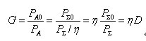
It can be seen from the above formula that the antenna gain G is the product of the antenna directivity coefficient and the antenna efficiency. In engineering, the antenna gain G is often expressed as
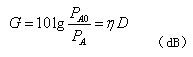
It should be noted that the standard antenna used to test the antenna gain is an ideal non-directional antenna, but in actual operation, there are also many half-wave symmetrical oscillators as reference antennas. Therefore, when looking at the antenna gain data, you should check which antenna is used as the reference antenna.
In addition to the above main parameters, the characteristic parameters of the antenna include effective height, frequency bandwidth, main lobe width describing the directivity of the antenna, ratio of main and side lobes, etc. You can refer to relevant materials.
2. Commonly used antennas for wireless communication
There are many types of antennas and different uses. There are three common types of wire antennas, array antennas and wide-mouth antennas in radio communications.


